
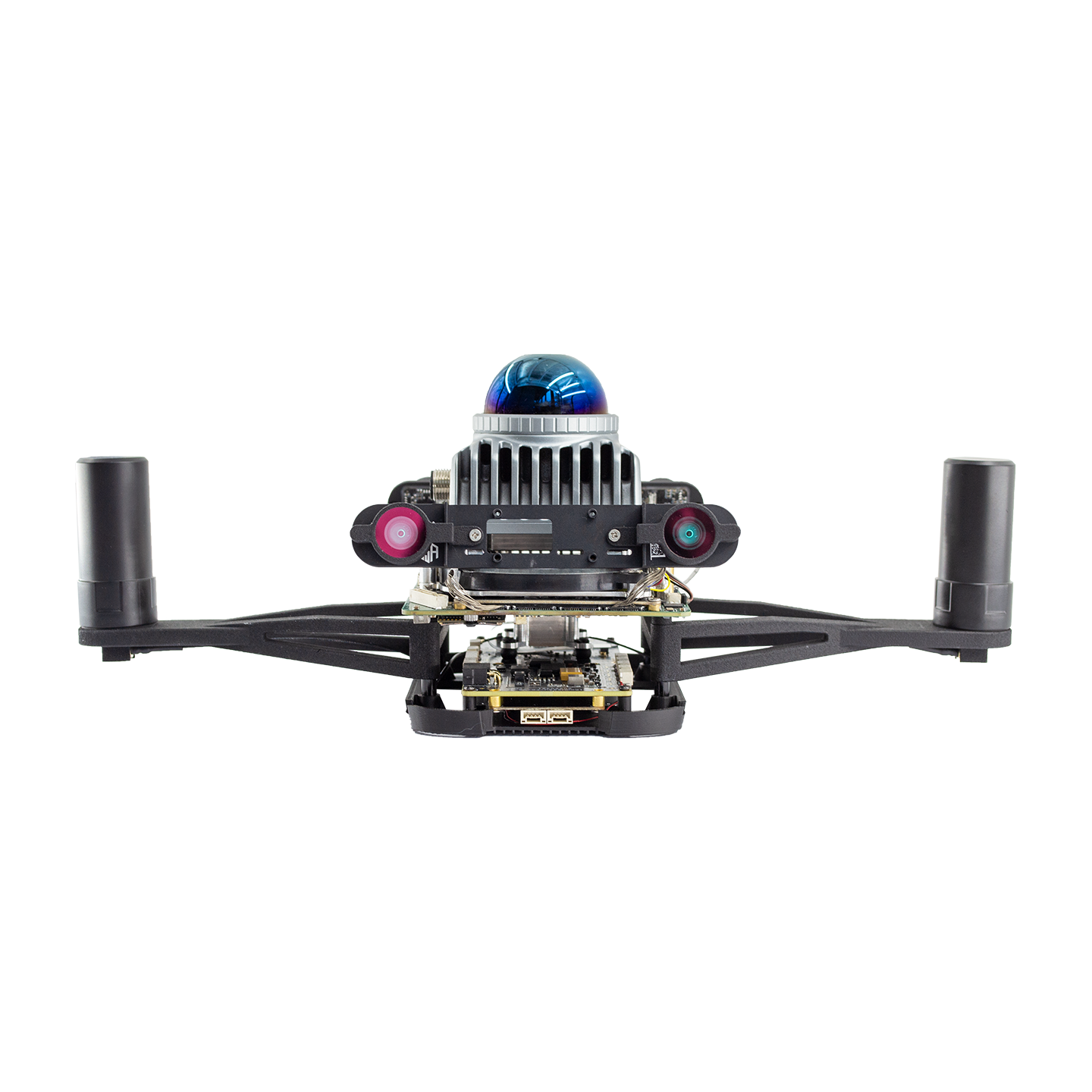




FlyCore UAV Control System
- $7,150.00
- $7,150.00
- Unit price
- per
Subtotal:
$7,150.00
Couldn't load pickup availability
Shipping
Shipping options and costs are calculated at checkout or confirmed in your quotation.
Delivery time depends on destination, customs clearance, and product availability.
Returns & Refunds
Eligible returns and refunds follow our Refund Policy.
Return shipping is handled according to the policy terms.

Description
xMedia
xFlyCore video resources from the ROBOSN channel, including autonomous exploration, FUEL reproduction, ground-station development, and the FlyCore hands-on series.
Reproducing the FUEL Algorithm on a Drone with AI
Watch on YouTubeEpisode 3: I Let AI Build a Drone Ground Station - Then Tested It in Real Flight
Watch on YouTubeEpisode 2: FlyCore Makes Building an AI Drone Much Easier Than You Think
Open channel videosEpisode 1: What Is FlyCore? A New Way to Build Your Own AI Drone
Watch on YouTubeShipping & Return
xFlyCore is shipped as an integrated UAV control system for technical integration projects. Final logistics, lead time, packing confirmation, and compliance checks are aligned with the selected configuration and destination before fulfillment.
Checkout shipping can vary by airframe, payload, packing requirements, and destination. AMOVLAB can confirm the freight plan in your quotation before dispatch.
AMOVLAB ships technical products globally where logistics and compliance allow. Freight, duties, taxes, customs clearance, and delivery time may vary by region.
Eligible returns and refunds follow the Refund Policy. Technical products may require order-status, condition, and configuration review before return approval.
Return shipping is not automatically free unless the return is caused by our error, a confirmed defective item, or another case covered by the policy.
FlyCore integrated control system
UAV autonomy that keeps working when GNSS does not.
FlyCore combines perception, positioning, planning, flight control, Web management, and PX4-compatible development into one integrated UAV control system for OEMs, integrators, research teams, and secondary-development projects.
FlyCore
GNSS-denied UAV control system
No GNSSStable autonomous positioning in GNSS-denied or weak-signal spaces.
IntegratedPerception, planning, control, sensors, and Web management in one platform.
PX4 readyCompatible with the PX4 open-source flight-control ecosystem.
BSA-SLAMPositioning and mapping workflow designed for real UAV deployment.
GNSS-denied scenarios
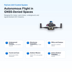
Built for the places where normal navigation breaks.
The original FlyCore detail page leads with real operating scenes. The storefront keeps that order: FlyCore is presented first as a UAV system for indoor, semi-indoor, and signal-blocked mission environments.
Operate in GPS-denied parking structures where satellite positioning is blocked and local perception is required.
Support inventory, inspection, and route validation workflows in structured indoor spaces.
Enable indoor flight verification, route tests, and algorithm validation without rebuilding the full stack.
Use onboard perception and SLAM workflows where lighting, geometry, and GNSS coverage are challenging.
Integrate GNSS, RTK, visual positioning, and mission payloads for open-area deployment.
Prepare UAV systems for mixed environments where positioning sources and control assumptions change.
Hardware base
Strong hardware foundation with multi-compute collaboration.
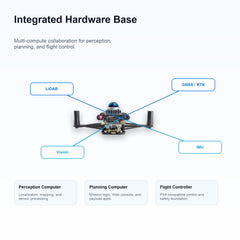
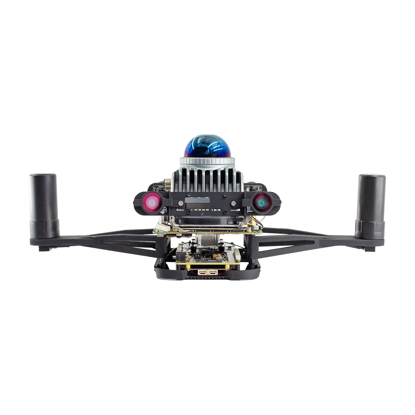
FlyCore is positioned as more than a flight controller. It is an integrated compute and control base with perception, planning, flight control, sensor input, and external payload interfaces.
Multi-unit collaboration
Perception, planning, and control are separated but coordinated.
The system separates high-load perception, application planning, and flight-control safety into dedicated compute layers. This keeps autonomy workloads organized while preserving a stable flight-control foundation.
- Perception computer for localization, mapping, and sensor processing.
- Planning and application computer for user logic and mission development.
- Flight-control computer for attitude control, actuator output, and safety fallback.
Perception sideVisual positioning, LiDAR, IMU, mapping, and BSA-SLAM processing.
Planning sideRK3588 application layer, Web console, payload logic, and user development.
Flight sidePX4-compatible flight control, MAVLink, power monitoring, and safety control.
Sensor inputFour vision channels, IMU, RTK/GNSS, LiDAR, and payload signals.
Data outputPositioning, control, mission state, network, serial, and Web service outputs.
IntegrationCommon power, communication, and mechanical interfaces for OEM aircraft.
Designed around cameras, LiDAR, IMU, GNSS/RTK, and external mission payloads.
Ethernet, serial, USB, MIPI, SPI, CAN, GNSS, payload, and flight-control links support real integration work.
Provides 12 V, 5 V, and 3.3 V auxiliary output rails for lightweight external modules.
Engineering value
Save engineering effort, cost, and deployment time.
The original detail page contrasts FlyCore against building a UAV stack from scratch. The product page keeps that message clear for integrators and engineering buyers.
FlyCore integrated approach
| Starting point | Integrated control system plus adaptable UAV platform. |
|---|---|
| Typical work | Aircraft adaptation, parameter tuning, payload integration, application development. |
| Deployment target | Product landing can be accelerated to roughly one month when requirements are aligned. |
| Business effect | Lower development risk, faster market entry, and a cleaner integration path. |
Traditional development path
| Starting point | Hardware selection, interface adaptation, hardware design, and sensor synchronization. |
|---|---|
| Typical work | Flight-control software, mapping and positioning algorithms, application code, and long validation cycles. |
| Deployment target | Often requires two to three years before a stable product is ready. |
| Business effect | Long cycle, high cost, and more uncertainty before field deployment. |
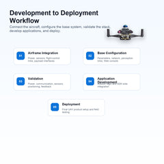
Development workflow
A complete path from integration to application deployment.
The workflow follows the polished detail page: connect the airframe, complete base configuration, validate the system, develop applications, and deploy the final integration.
Mount FlyCore on the UAV frame, connect power, flight-control links, sensors, and payload interfaces.
Configure flight controller parameters, perception links, network addresses, and Web console access.
Verify power stability, communication, sensor output, positioning status, and flight-control feedback.
Develop mission logic on the planning computer using the provided interfaces and SDK environment.
Integrate the system into the final UAV product, document the configuration, and prepare field tests.
Software ecosystem
PX4-compatible, BSA-SLAM enabled, and transparent from hardware to application.
FlyCore is designed for teams that need the freedom of an open UAV ecosystem without rebuilding every core subsystem themselves.
Keep using the PX4 open-source ecosystem while integrating FlyCore perception, positioning, and application layers.
Use a SLAM workflow prepared for UAV localization, map management, and positioning output to the flight controller.
Manage maps, parameters, logs, OTA packages, plug-ins, and runtime state through the built-in Web console.
AI-assisted development
Prepared for secondary-development teams and UAV integrators.
FlyCore gives developers a clearer boundary between flight-control safety, perception positioning, and user application logic. That makes AI-assisted Web ground-station development, payload control, and mission app integration easier to plan.
- Application-side development can run on the planning computer.
- Web interfaces expose map, parameter, log, plug-in, and OTA workflows.
- Mission payload integration can use serial, network, MIPI, USB, and power outputs.
Web consoleMaps, parameters, plug-ins, logs, OTA, and runtime monitoring.
Developer appsUser mission logic, AI-assisted interface work, and payload control.
Flight stackPX4-compatible control, MAVLink communication, and safety states.
Specifications
Readable parameters for engineering comparison.
Key technical data is rebuilt as English HTML tables so buyers and search engines can read it directly.
System capability
| Effective perception distance | >= 5 m at 90% reflectivity and 100 klx. |
|---|---|
| Perception blind zone | <= 30 cm, depending on the final sensor layout. |
| Effective perception range | >= 180 degrees, depending on the final sensor layout. |
| Perception resolution | <= 5 cm. |
| Perception output frame rate | >= 10 Hz. |
| Positioning output jitter | <= 10 ms interval fluctuation. |
| Static positioning error | +/- 5 cm and +/- 1 degree, 5 min CEP95. |
| Dynamic positioning error | +/- 15 cm and +/- 3 degrees, 5 min CEP95. |
| Initialization time | <= 20 s. |
| Maximum recommended motion speed | 5 m/s. |
Compute and storage
| Perception CPU | Hybrid processor with up to 4.8 GHz P-core, 3.8 GHz E-core, and 2.4 GHz LE-core. |
|---|---|
| Perception GPU / NPU | Intel Graphics up to 2 GHz; 12 TOPS INT8 NPU. |
| Perception memory / storage | 16 GB LPDDR5; 256 GB 2242 NVMe PCIe 3.0 x2. |
| Planning CPU | RK3588L, up to 2.4 GHz. |
| Planning GPU / NPU | ARM Mali-G610 MP4; 6 TOPS INT8 NPU. |
| Planning memory / storage | 16 GB LPDDR4X; 128 GB eMMC. |
| Visual front end | OAK-SOM-Pro. |
Electrical and mechanical
| Camera channels | 4 perception camera channels. |
|---|---|
| Time synchronization | IEEE 1588-2008 and PPS output. |
| Operating temperature | -10 to 50 deg C with standard cooling and good ventilation. |
| Humidity range | 0 to 90% RH, non-condensing. |
| Input power | 15 to 28 V at 5 A. |
| Mechanical size | 120 x 93 mm. |
| Maximum design power | 40 W, excluding external output power. |
| External power outputs | 12 V at 3 A, 5 V at 2 A, 3.3 V at 1 A. |
External interfaces
| Integrated external ports | 100 Mbps Ethernet x2 and command/control serial x2. |
|---|---|
| Perception camera ports | MIPI 2-lane x4. |
| Onboard IMU | SPI x1. |
| Payload interface | Serial x1, MIPI 4-lane x1, and USB 2.0 x1. |
| USB-C | USB 3.0 x2 and DP support. |
| GNSS and timing | GNSS serial x1 and PPS input x1. |
| Flight controller and data link | Serial x1 and 100 Mbps Ethernet x1. |
| Certification target | CCC, CE, FCC, and RoHS. |
Packing list
Core kit prepared for integration work.
The final package should be confirmed before publishing, but the English storefront keeps the same checklist structure from the polished detail page.
| Item | Quantity |
|---|---|
| FlyCore control system main unit | 1 |
| Radar mounting structure | 1 set |
| Power cable U | 1 |
| TF card | 1 |
| Power module | 1 |
| Type-C cable | 1 |
Build a GNSS-denied UAV product around FlyCore.
Use FlyCore as the integrated foundation for positioning, perception, planning, control, and Web-based management. AMOVLAB can help align the aircraft, payload, power, and software stack with your target deployment scenario.
Related Products
- Choosing a selection results in a full page refresh.


